 |
|
NEW!
|
New! Dial in and
New Music for June 2022!
|
The facts about, electrical hazards and safety issues aging
Hammond organs.
Part sales are for our customers. We are not in the parts retail business.
|
 |
In both the Hammond B2, C2 and RT2 (manufactured prior to 1955) original rubber insulated wiring dries out cracks and crumbles. This is both a shock and fire hazard.
The Hammond B2 or C2 in your church, home or studio should be rewired to prevent this potential fire hazard. We use only high quality UL/CSA listed 16 and 14 AWG wire for replacing all AC wiring in the organ as well as dual conductor balanced audio cabling with an overall stranded braid and 100% foil shielding to help prevent hum and other interference from the AC wiring in the console conduit leading to and from the outlet box.
|
The Hammond B2/C2 preamplifier power transformer
|
 |
In both the Hammond B2, C2 and RT2 (manufactured prior to 1955) have transformers which are dipped in wax before they are enclosed in their respective end covers. Over time this wax melts out from the heat leaving a potential problem for shorts within the windings as well as the outer parts of the transformer causing it to over heat leading to a potential fire hazard as well as a shock hazard. To help prevent problems the preamplifier's AC leakage to ground should be checked to determine if the transformer is starting to fail and proper fusing must be added to prevent a potential hazard.
We have the experience and equipment to test and correct these problems.
|
The problem with the Hammond B2/C2's 6X5 Rectifier Tube
|
 |
In both the Hammond B2, C2 and RT2 preamplifier, the 6X5 or 6X5GT is the rectifier tube used in these organs. The 6X5 consists of 3 parts: filament, cathode and plate. In the case of the 6X5 the filament is wound in spiral within cathode inside the which is a small cylindrical piece of metal as can be seen protruding out the top of the mica insulator. The filament and cathode are insulated (from each other) with a very small film of oxide on the cathode. As the 6X5 rectifier tube ages this oxide film breaks down and the filament starts to conduct (short out) to the cathode. When this happens it creates a short circuit which is reflected back into the power transformer's wiring. As it continues to break down the extra current drain on the transformer increases drastically and over heats the power transformer to the point of becoming hot to the touch. The power transformer will either fail (burn out) from over heating or can short out completely and making it a fire hazard. To keep this from being a problem, it is a must that proper fusing be added to prevent damage to the transformer and therefore the high replacement cost of this part when a 6X5 fails. It is much cost effective to replace a vacuum tube which amounts to a few dollars and install proper fusing rather than replacing the power transformer which is becoming quite rare and can cost up to several hundred dollars.
|
Problem components under the chassis of the Hammond B2/C2 Preamplifier.
|
 |
The B2/C2's preamplifier consists of components named Capacitors and Resistors. In this view there are two different kinds of capacitors. Those circled in purple are paper dipped in wax. These types of capacitors were used throughout the industry in a multitude of electronic products during the late 1940s to the early 1950s. Because of there composition being dipped in wax, they absorb moisture which cause their values to change drastically. Wax capacitors are considered extremely unreliable. After being in service for 50+ years they should always be replaced. Bad paper/wax capacitors can cause the organ to sound dull and pose a great risk for damaging expensive components like the power and output transformers when they break down and short circuit. These are easily replaced with modern components which will bring back the warmth as well as brightness to the instrument. The metal can type oil filled capacitors circled in green have a tendency to dry out and therefore start to conduct causing random popping and at times 'thunder' noises in the Leslie or Hammond tone cabinet. These are very prone to failure after being in service for 50+ years and should be replaced. The third components which are resistors which are circled in pink commonly stretch with age and can cause the preamplifier to not operate at it's full potential. These should be checked 'measured' with a multi-meter to determine if any have stretched beyond specification.
A preamplifier first should have it's capacitors replaced, "half-rebuild" and a full rebuild if many of the resistors show to have changed by more than 10% of their original values. All of these components are very inexpensive and can dramatically improve the sound of any Hammond B2 or C2 therefore giving it many more years of musical enjoyment!
|
Electrical hazards and safety issues common to the Hammond B3, C3, A100, and
RT3 model Preamplifiers.
|
Electrical safety issues of the Power Transformer in the B3, C3, A100
and RT3 preamplifiers.
|
 |
In the Hammond B3/C3, A100 and RT3 (manufactured 1955 and) like the B2 and C2 have transformers which are dipped in wax before they are enclosed in their respective end covers. Over time this wax melts out from the heat leaving a potential problem for shorts within the windings as well as the outer parts of the transformer causing it to over heat leading to a potential fire hazard as well as a shock hazard. To help prevent problems the preamplifier's AC leakage to ground should be checked to determine if the transformer is starting to fail, and proper fusing must be added to prevent a potential hazard.
We have the experience and equipment to test and correct these problems.
|
Electrical hazards and safety issues of the 6X4 Rectifier tube in the Hammond B3, C3, A100, and RT3 model organs.
|
 |
In the Hammond B3, C3, A100, and RT3 preamplifiers, the 6X4 which is the later version of the 6X5 (mentioned above) is the rectifier tube used in these model organs. The 6X4 consists of 3 parts: filament, cathode and plate. In the case of the 6X4 the filament is wound in spiral within cathode inside the which is a small cylindrical piece of metal as can be seen protruding out the top of the mica insulator. The filament and cathode are insulated (from each other) with a very small film of oxide on the cathode. As the 6X4 rectifier tube ages this oxide film breaks down and the filament starts to conduct (short out) to the cathode. When this happens it creates a short circuit which is reflected back into the power transformer's wiring. As it continues to break down the extra current drain on the transformer increases drastically and over heats the power transformer to the point of becoming hot to the touch. The power transformer will either fail (burn out) from over heating or can short out completely and making it a fire hazard. To keep this from being a problem, it is a must that proper fusing be added to prevent damage to the transformer and therefore the high replacement cost of this part when a 6X4 fails. It is much cost effective to replace a vacuum tube which amounts to a few dollars and install proper fusing rather than replacing the power transformer which is becoming quite rare and can cost up to several hundred dollars.
|
Fusing and heat shrink installed in the Hammond B3, C3, A100, RT3 and D100
Preamplifiers and the RT3 and D100 Pedal Solo Unit.
|
 Hammond B3, C3, RT3 preamplifier Chassis
 Hammond RT3 and D100 Pedal Solo Unit Chassis
|
As shown, proper fusing added to the preamplifier chassis for B3, C3, and RT3 preamplifiers as well as the RT3, D100 Pedal Solo Unit Chassis. In the cases where an instrument is resting on concrete or some other surface with an 'earth ground potential', double fusing should be installed across both primary wires of the respective power transformers.
Older transformers have cloth insulation. As an added precaution heat shrink tubing is added to the power transformer during disassembly for inspection and cleanup of zinc oxide and repainted with a nonconductive clear paint.
|
 |
Above is an outlet box of a Hammond B3. The B2/C2 as well as the C3 use a similar type of outlet box. Notice the broken 6 pin Amphenol socket. This damage is caused by numerous reasons namely stress on the socket which could be from various things such has having pulled the cable from the side causing the outer housing to break, stepping on the cable connector which will also cause the outer rim of the connector to break off. Not only is this connector now loose in the outlet box which makes it difficult to securely plug the Leslie cable in correctly but the exposed portions on the on the other side of the socket are not insulated and connected to 120 volts AC on pins 3 and 4 which if allowed to continue this way will short out against the metal of the casing and cause a short circuit which in turn becomes a serious electrical shock and/or fire hazard.
|
Problem components under the chassis of the Hammond B3/C3, A100,
RT3 preamplifiers and the RT2, RT3 Pedal Solo Unit.
|
Hammond Preamplifier chassis underside for the B3, C3, A100, RT3 and D100 Consoles models.
 Hammond Pedal Solo Unit Chassis Underside for the RT3
and D100 Console Models.
 |
The B3/C3, A100, RT3, D100 and RT2, RT3, D100 Pedal Solo Units these circuits consist of components named Capacitors and Resistors. In this view there are two different kinds of capacitors. Those circled in purple are paper with either cardboard or ceramic casings. These types of capacitors were used throughout the industry in a multitude of electronic products during the late 1950s to the early 1960s. Because of there composition the porous ceramic cased types they absorb moisture which cause their values to change drastically. All paper capacitors no matter what type of casing they are enclosed in are extremely unreliable and should always be replaced. In the RT and RT2 wax dipped capacitors were used in earlier versions of this unit.
After being in service for almost 50 years they should always be replaced. Aging paper capacitors can cause the organ to sound dull and pose a great risk for damaging expensive components like the power and output transformers when they break down and short circuit. In the case of the RT2, RT3 and D100 Pedal Solo Units, they can cause drifting in tuning, difficulty in tuning the Pedal Solo Unit or become so unstable it can't be tuned at all. These are easily replaced with modern components which will bring back the warmth as well as brightness to the instrument. The second component is electrolytic capacitors which is circled in gray are used as part of the power-supply circuit. As they age the oil within the can dries out causing the power supply circuits to operate below standard which will cause increased audio hum and will cause a loud growl in the audio when they completely fail. The third components which are resistors which are circled in pink commonly stretch with age and can cause the preamplifier to not operate at it's full potential. These should be checked 'measured' with a multi-meter to determine if any have stretched beyond specification.
A preamplifier first should have it's capacitors replaced, "half-rebuild" and a full rebuild if many of the resistors show to have changed by more than 10% of their original values. All of these components are very inexpensive and can dramatically improve the sound of any Hammond B3, C3, A100, RT3 or D100 and the stability of the Pedal Solo Unit in the Hammond RT2, RT3 and D100, therefore giving it many more years of musical enjoyment!
|
Electrical hazards and safety issues common
to all Hammond A100 models
|
  |
In Hammond A100s the main amplifier consists of one 5U4 rectifier and two 6BQ5 Beam Power Vacuum tubes. Unlike earlier power transformers in the B3/C3, RT3 and D100 preamplifiers they do not suffer the same potential for electrical problems in that they are dipped or 'potted' in tar instead of wax. This leads to increased reliability and longevity of the power transformer, however in the case of the 5U4 rectifier as it ages, the filament can break somewhere along the base of the vacuum tube and spring outward causing it to touch the plate (black area of the tube) which creates a direct short. This in turn will cause the power transformer to burn up as well as burning several components in the power supply chain. This poses a very serious fire hazard. To prevent this, it is a must that proper fusing be added to this amplifier's chassis.
|
Safety Issues and Electrical Hazards of the A100s Reverb Amplifier.
|
  |
In the Hammond A100, the 6CA4 which is the rectifier tube (very similar to the 6X4 and 6X5) (mentioned above) is the rectifier tube used in this model organ. The 6CA4 consists of 3 parts: filament, cathode and plate. In the case of the 6CA4 the filament is wound in spiral within cathode inside the which is a small cylindrical piece of metal as can be seen protruding out the top of the mica insulator. The filament and cathode are insulated (from each other) with a very small film of oxide on the cathode. As the 6CA4 rectifier tube ages this oxide film breaks down and the filament starts to conduct (short out) to the cathode. When this happens it creates a short circuit which is reflected back into the power transformer's wiring. As it continues to break down the extra current drain on the transformer increases drastically and over heats the power transformer to the point of becoming hot to the touch. The power transformer will either fail (burn out) from over heating or can short out completely and making it a fire hazard. To keep this from being a problem, it is a must that proper fusing be added to prevent damage to the transformer and therefore the high replacement cost of this part when a 6CA4 fails. It is much cost effective to replace a vacuum tube which amounts to a few dollars and install proper fusing rather than replacing the power transformer which is becoming quite rare and can cost up to several hundred dollars.
|
Problems common to all Tone Wheel type Hammond Organs.
The Drawbar Base of the Hammond Organ
|
 |
Drawbars can become intermittent from tarnish and dirt lodged in the buss bars as well as becoming difficult to move from hardened grease. Wires commonly break off the Drawbars causing all of the tones for that drawbar to not play. These should be inspected and cleaned regularly when scheduled general maintenance is performed.
|
The Preset Panel within Tone Wheel Hammond
|
 |
The Preset Panel wiring which is common in all tone wheel Hammond organs connects all the preset wiring via screws on the bus bars. These loosen over time and cause stray tones to sound when no keys pressed and/or loss of harmonics while playing. These should be inspected and tightened when regular maintenance is performed.
|
The main terminal strip on the Tone
Generator within the Hammond Organ
|
 |
The tone generator terminal strip is where both upper and lower manuals and pedal wiring harness are connected to the tone-generator. Wires from either harness can break loose from the terminal strip by accident or from stress on taut wiring harness. This can cause anywhere from a few lost harmonics to many lost notes on both of the upper and lower manuals as well as the pedal division.
|
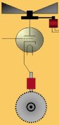
The Synchronous Motor and Vibrato Scanner
in the Hammond Organ
|
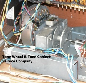 |
Common problems with the Hammond Synchronous Run Motor are broken oil threads which can cause excessive wear on the front and rear bronze bushings. This will either causes the bushings to wear out causing armature wobble and or run motor seizure. The 16 pole Vibrato Scanner like many other metal parts of the organ are plated with Zinc. Over time the Zinc tries to return to it's crystalline form which cause hair like particles to grow inside the scanner as well as on other parts. This will in turn cause partial or complete failure of the Vibrato/Chorus functions. Evidence of this is choppy sounding Vibrato (motor boating) only a very small amount of sound passing through the vibrato scanner, like a "blipping" noise or no signal passage at all. Broken oil threads of the Vibrato scanner will cause the scanner's rotor to seize and therefore the Vibrato/Chorus will not function. The correct procedure is to completely disassemble clean, paint all metal parts with a nonmetallic, nonconductive coating, replacing all of the oil threads of both the scanner and run motor assemblies which have are quite deteriorated and most always break during reassembly.
|